Digital manufacturing - Week One: design Brief
Author: Callum Baxter Date: 02/02/2023 Topic: Digital Design and Manufacturing
Introduction
I am currently studying towards an MSc in Digital Design and Manufacture at Print City, an award winning teaching and research centre for Manchester Metropolitan University. This blog will detail my progression through a module in Digital Manufacturing and catalogue my knowledge and use of sophisticated manufacturing technologies and software. This course started on Wednesday, 1st of February 2023 and is set to conclude on Friday, 19th of May 2023 with the submission of this blog as evidence that I have achieved the earning outcomes for this module. There is also an interim submission where we are required to submit a set of additively manufactured phones cases that integrate within a complex manufacturing production line produced by Festo CP Labs.
This first blog post will describe and explain the first week of teaching where I met my tutors, I was presented with a design brief and I was taught how to interpret and model a product using an engineering drawing as a reference.
Brief Specifications
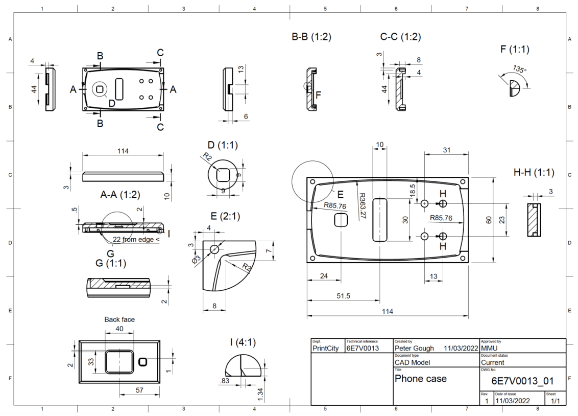
During the first week of teaching I was presented with a brief that required me to model and additively manufacture the top half of a set of phones cases. I was also provided with the hypothetical context that 50,000 phone cases needed to be produced annually and that each of these phone cases needed to integrate flawlessly within an existing production line. It was therefore essential that each phone case was traceable, consistent in quality, and fit together with the bottom half exactly. The engineering drawing (Fig.1) shows the dimensions of the top half of the phone case that I was asked to produce. This was not an exercise to improve the phones case in any way, but instead a task that asked us adhere strictly to a predetermined set of exact specifications.
Fig. 1: This engineering drawing provided exact specifications for the modelling and manufacture of the phones cases.
Parametric Modelling
Autodesk Fusion 360 was used to parametrically model the phone case. Fusion360 is a computer aided design, engineering and manufacturing software that also has functionalities for PCB design and simulation. The programme allows for complex functional products to be designed and for individual parts to be mechanically simulated using methods such as finite element analysis. Additionally, many manufacturing processes are integrated within the software and allow parts to be manufactured within a virtual environment before committing to real-world production. This is important when trying to identify design errors and process inefficiencies.
Fig.2 shows some of the steps involved in the modelling process. This part was not highly complex, so replicating it was not difficult and the design process only took about an hour to complete. It was useful to carefully examine the phone case and critically evaluate potential manufacturing processes whilst designing. I determined that a prototype model could be produced using any of the following manufacturing processes without difficulty:
Fused Deposition Modelling
Stereolithography
Selective Laser Sintering
Fig.2: Images showing the modelling process for the phone case.
Finished Prototype Model
Once the model was finished, all it’s dimensions were checked against the engineering drawing as a quality control measure. Below is an interactive model that represents the final CAD model.
References
No information was referenced within this Blog Post.


